[Shortcut Key Chart] Basic operations and initial settings for Blender
Blender is a python-based software mainly used for 3DCG production, and can be used for 3D modeling, sculpting modeling, geometry modeling, UV expansion, texturing, rendering, and many other purposes.
However, many beginners may not know how to operate Blender, or may not know the shortcut keys.
Therefore, this article summarizes the basic operations of Blender and the shortcut keys used for them. We have also prepared a quick guide to shortcut keys, so we hope you will find it useful in your future production activities.
Blender Shortcuts Quick Reference
This is a quick guide to Blender shortcuts. Please download and use it.


Blender Initialization
Here are some settings that you should set up first to make Blender easier to use. Edit tab” and click on “Preferences”.
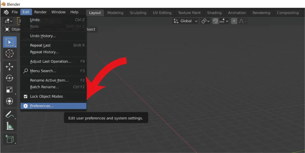
How to set up Japanese (language settings)
In addition to the default English, Blender also supports many other languages such as Japanese and Chinese. This article is written in Japanese.
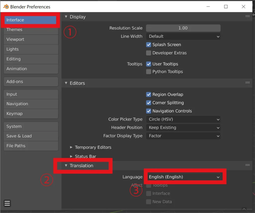
After opening “Preferences” from the “Edit tab”, click on the tab next to “Language” in the “Interface tab”. Translation” and click on the tab next to “Language” in the “Interface tab”.
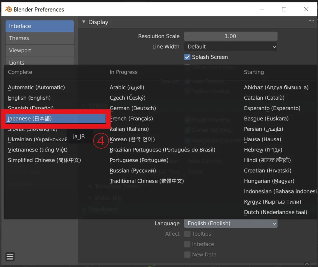
All displays can be changed to Japanese by selecting “Japanese” from the opened screen.
Viewpoint control settings
Next, we will discuss viewpoint control settings. Since viewpoint manipulation is important in any 3D software, it is recommended that you use settings and tools that are easy for you to use.
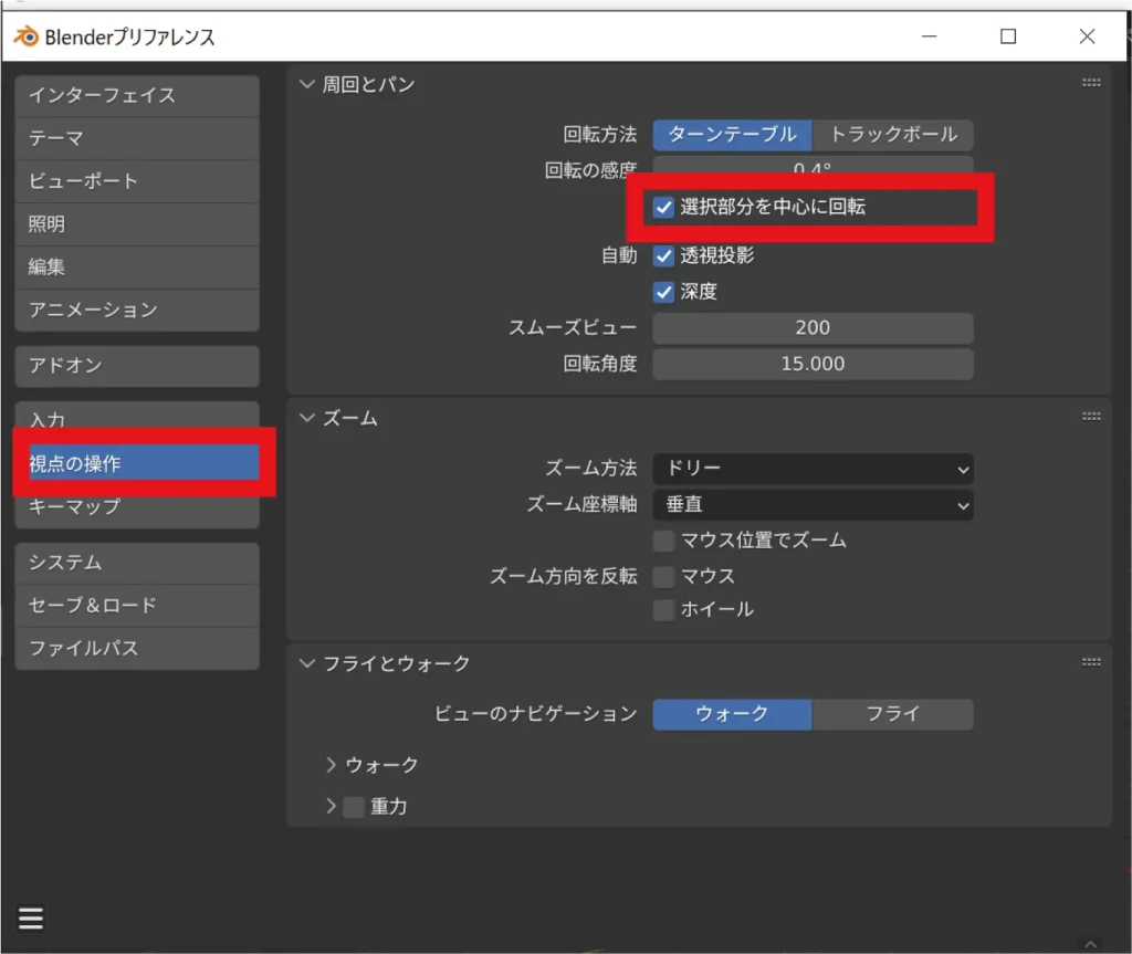
In the “Viewpoint Manipulation” tab, check the “Rotate around selection” checkbox under the “Perimeter and Pan” item.
This setting allows you to literally move the camera and viewpoint around the currently selected area. This is a useful setting that significantly reduces the chance of getting lost in the 3D screen.
Viewpoint manipulation in Blender
From here, we will explain the viewpoint operations in Blender in detail. We will explain in an easy-to-understand manner with illustrations, so please refer to this section.
Note that Blender’s viewpoint operations differ slightly from those of other 3D software. It is possible to change it from the settings, but once you get used to it, it is relatively easy to operate. Therefore, beginners are recommended to use the default settings.
Basic viewpoint operation
The first step is to manipulate the viewpoint, which can be done by operating the mouse.
Rotate around selection
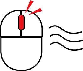
Middle mouse click ( mouse wheel click ) to drag.
Click to move the viewpoint around the selected point or object.
move sideways
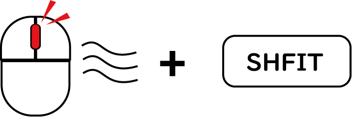
Middle mouse click-hold + SHIFT to drag.
It is possible to move the viewpoint parallel to the direction you are currently facing.
Zoom in/out
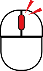
Scroll with the mouse wheel of your mouse.
You can move your viewpoint closer or further away from the center of the selected point or object.
To operate with the on-screen interface
Although mouse operation is more intuitive, operation via the screen interface is also possible.
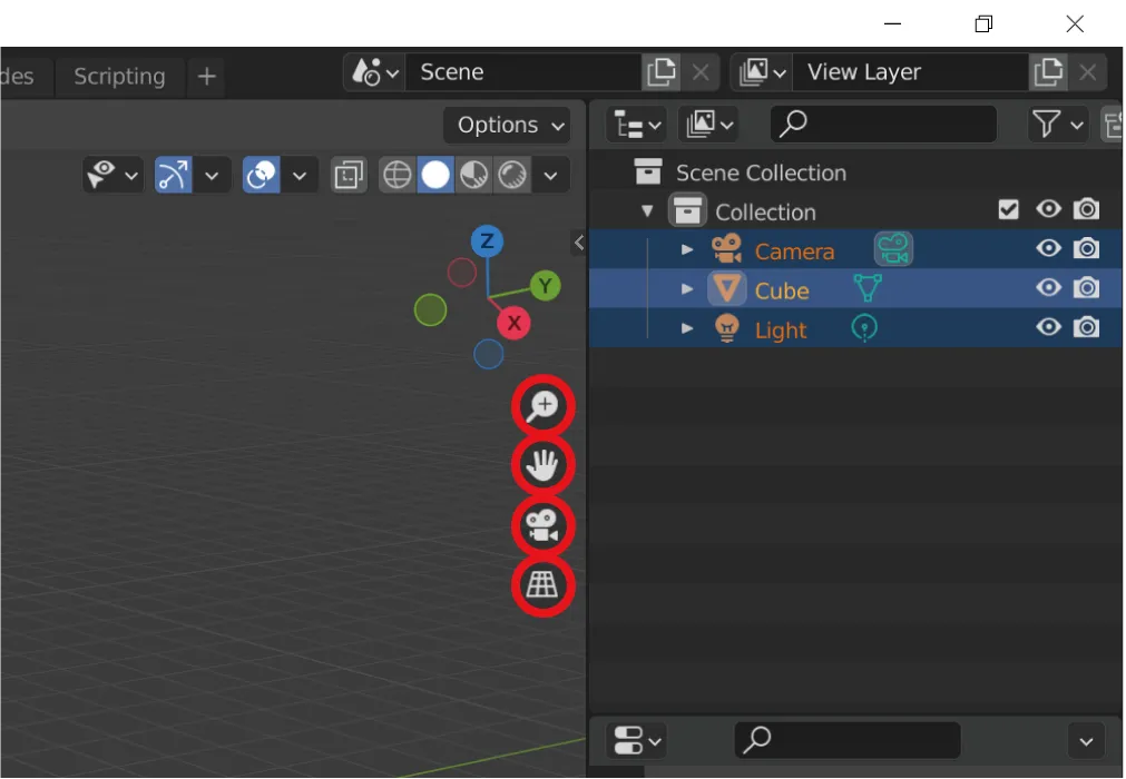
- Magnifying glass symbol: zoom in/out
- Hand symbol: move horizontally
- Video camera symbol: rotate around selection
- Table symbol: Apply or remove perspective (isometric view)
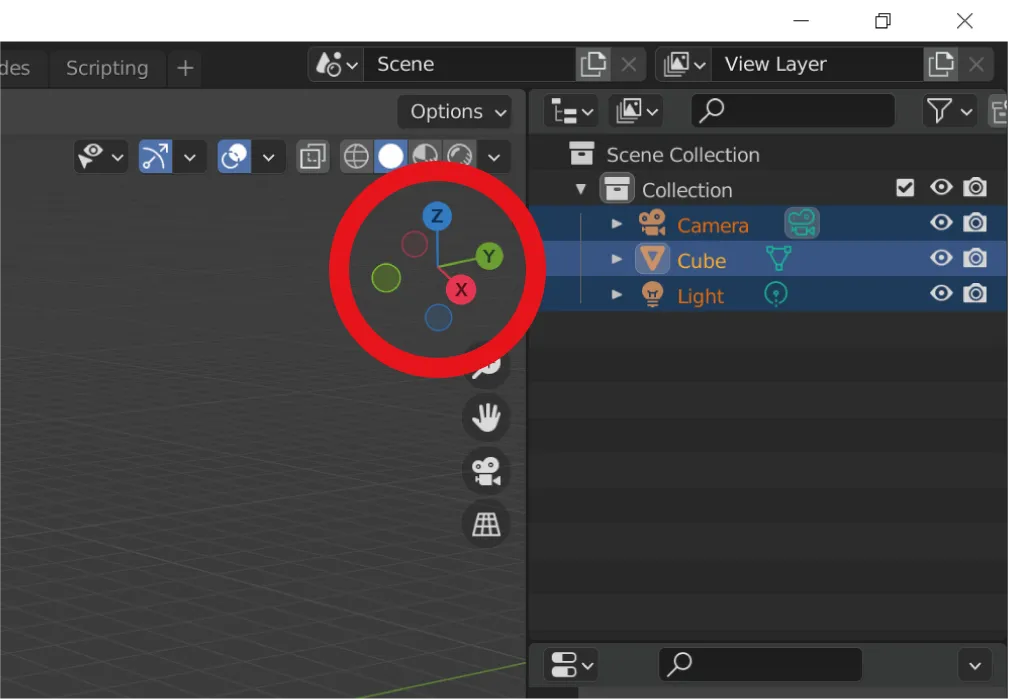
The XYZ axis indicator allows you to see from which angle you are currently looking when you move the viewpoint. You can also click on these XYZ letters to edit them in the front, top, and side view views, respectively.
[Basic] How to perform basic Blender operations
Blender is famous for its intuitive modeling operations, which can be achieved by learning a wide variety of shortcut keys and functions. With that in mind, this section will focus on how to operate modeling tasks with shortcut keys.
In basic modeling in Blender, there are roughly the following two modes.
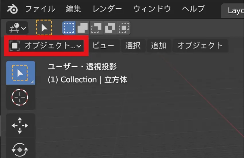
Object mode: Mode used to adjust the overall position and size of three-dimensional figures (objects) and use other functions.
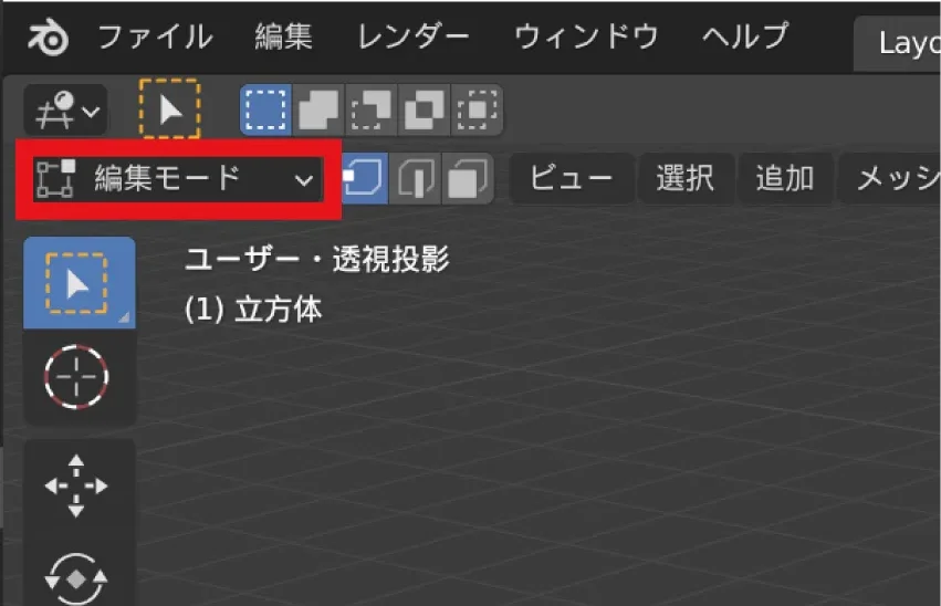
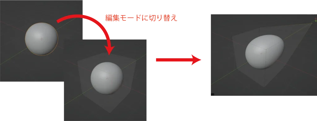
Edit mode: This mode is mainly used for modeling. The shape of the object itself can be created and edited using three elements: points, edges, and faces.
The above two modes can be toggled with “TAB” on the keyboard.
Edit Mode Operation
First, we will explain how to operate in edit mode. Before starting, make sure that the current mode is the object mode.
Delete initial light, camera, and cube objects
First, perform this operation to create a clean slate.
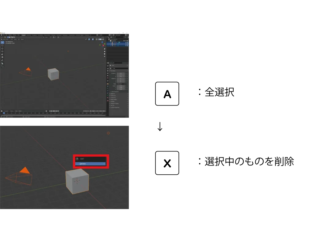
Place the mouse cursor inside the 3D view mode, press the keyboard in the above order, and click Delete.
Adding a new object
To add a new object, enter the following shortcut
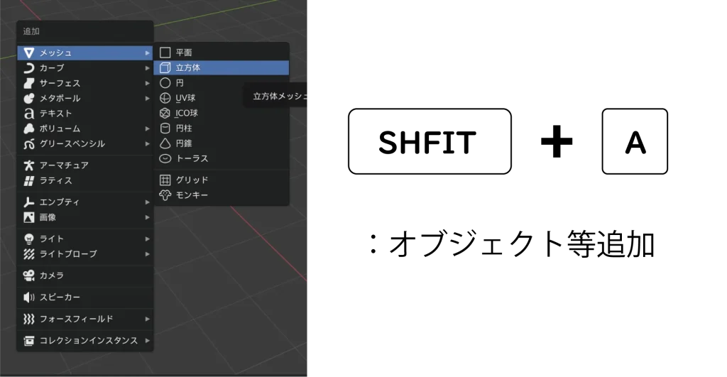
Then a menu will appear, and click on the cube in the mesh to make the cube appear on the screen.
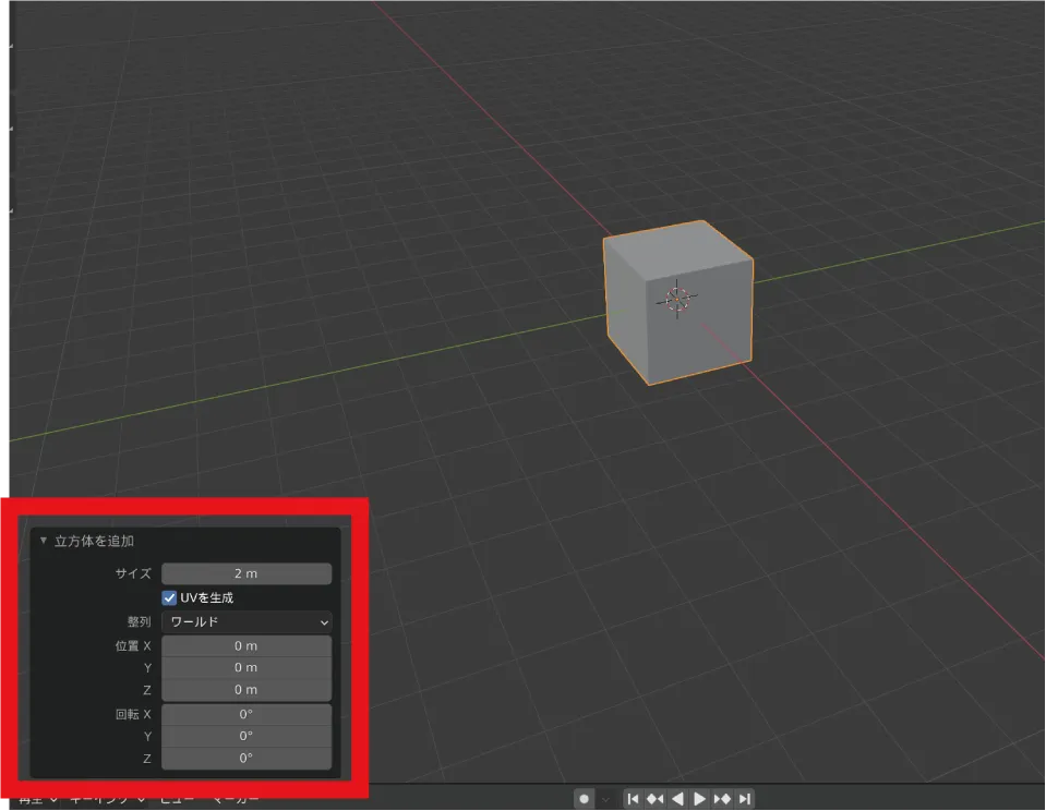
Confirmation of setting items
When an object is added, the respective setting item will appear in the lower left corner. If the object is closed, clicking on it will open it as shown in the image below.
Switch to edit mode
Now that the object has been added, enter edit mode.
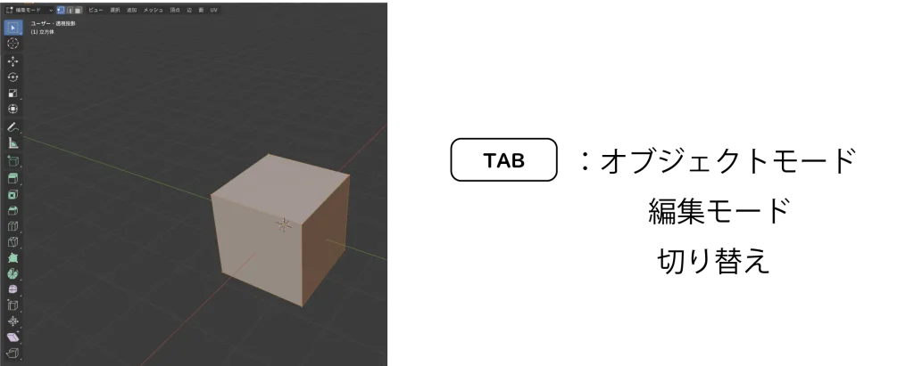
Press “TAB” to enter the edit mode, and various tools will appear on the left side as shown here.
Introduction of shortcut keys
In this article, we will introduce only the basic shortcut keys.

Click on a point, an edge, or a face of the cube using the numbers at the top of the keyboard, and the cube will appear in yellow, indicating that it has been selected. You can also switch between them by clicking on the red frame in the upper left corner of the screen.
The following are the main shortcut keys. Switch to faces and select one of the faces of the object.
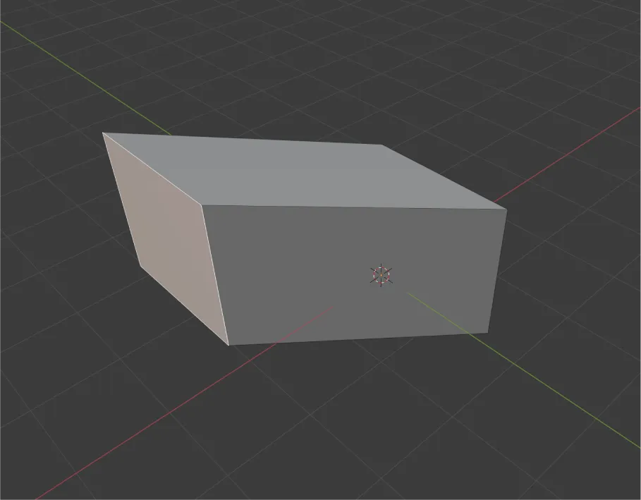
First, here is a shortcut for moving. Press “G” on the keyboard to move the mouse. You can move the selected plane parallel to the current viewpoint direction by mouse operation. By clicking, you can finalize the spot.
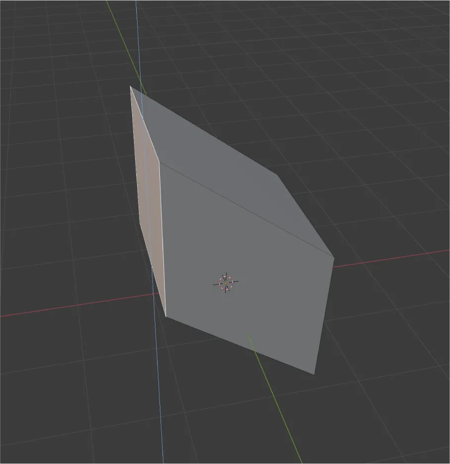
If you make a mistake, you can use “Ctrl+Z” to move back to the previous operation.
Pressing “G→X”, “G→Y”, or “G→Z” with “G” as the starting point allows you to move with the axis fixed.
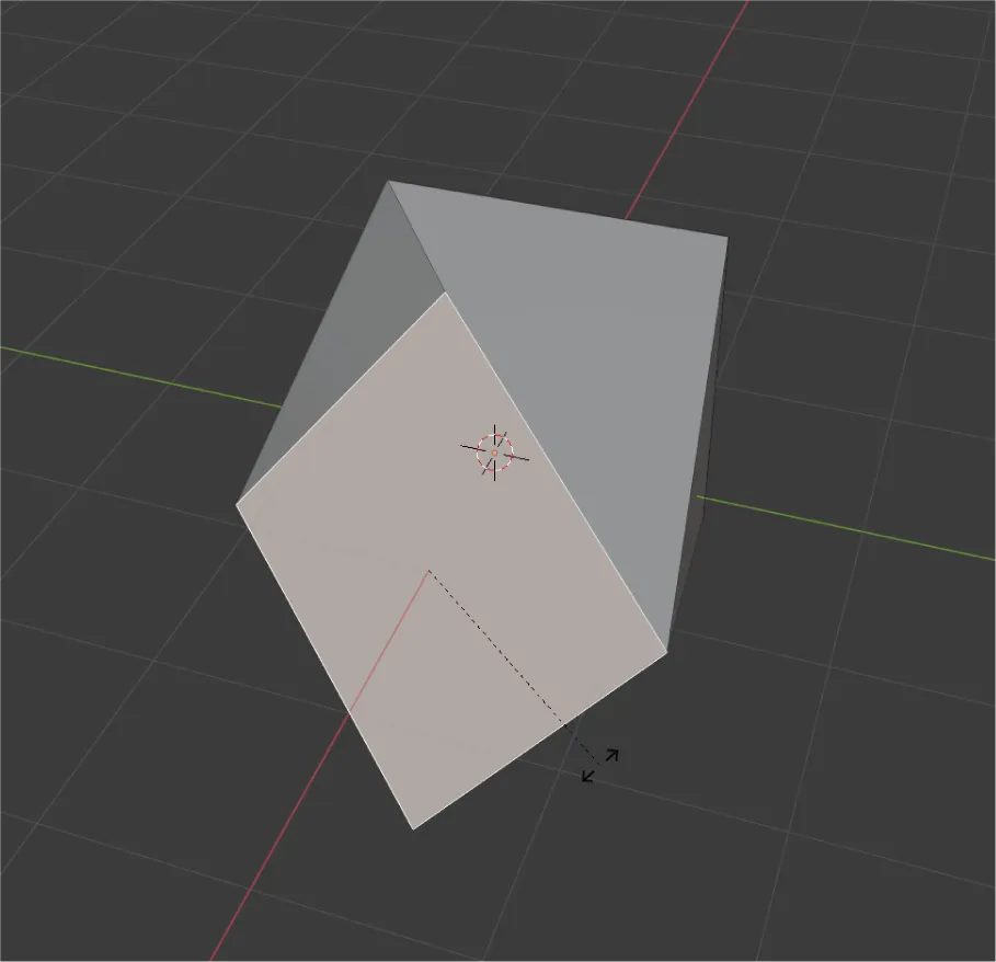
Press “R” to rotate the selected surface around the current viewpoint orientation. This can also be fixed by clicking. Rotation can also be fixed by pressing R and then X, Y, or Z to fix the axis. If you press “R” again after pressing “Rotate,” you can rotate freely without fixing the axis.
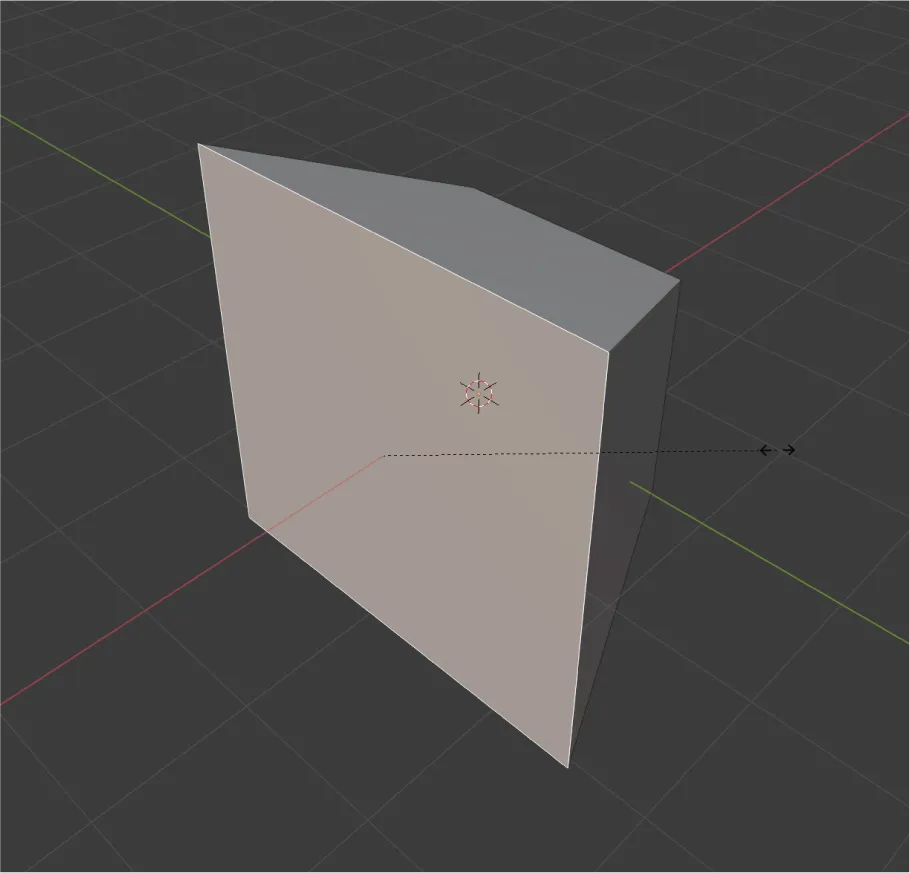
Next, we introduce scaling. Press “S” to change the size. The X, Y, and Z axes can also be fixed.
Each of the operations described above can be used for any point, edge, or plane. Also, it is possible to perform each operation after selecting a range or multiple selections using “SHIFT” when selecting.
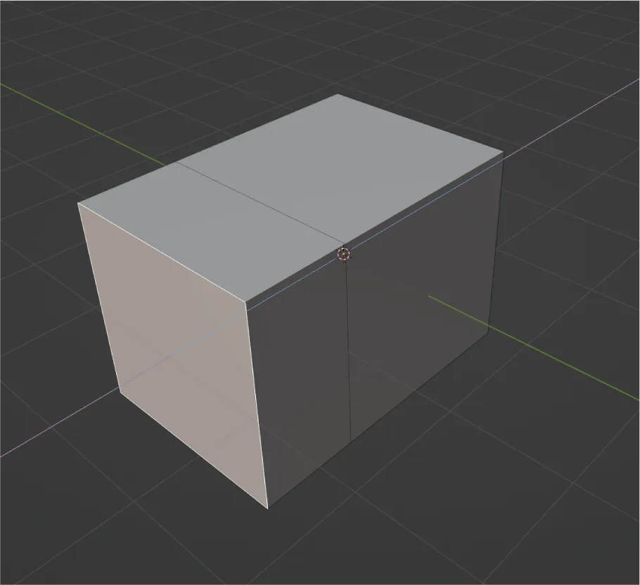
Finally, we introduce the extrusion. Select any of the surfaces you want and then press “E”.
This one is a bit special and allows you to extrude a face of the same size while maintaining the angle of the selected face.
By using the shortcuts introduced so far, you can already do basic modeling.
All of these operations can also be adjusted by entering numerical values from the menu in the lower left corner.
Translated with www.DeepL.com/Translator (free version)
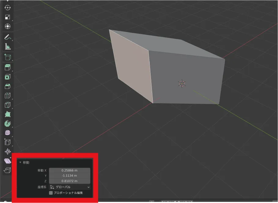
In Blender, the default unit is m (meter). Adjust the unit according to the output format.
Object mode (modifier)
The introduction of modifiers in object mode is explained next. A modifier is a convenient function that allows you to add additional deformation to an object created in Edit mode, like an effect.
Note that the same basic operations of movement, rotation, and scaling can be performed in object mode as well, so we will not discuss them here.
Here, we will use the introduction of the “boolean” modifier as an example. Booleans are explained again later in the article, so please refer to that section for details.
Translated with www.DeepL.com/Translator (free version)
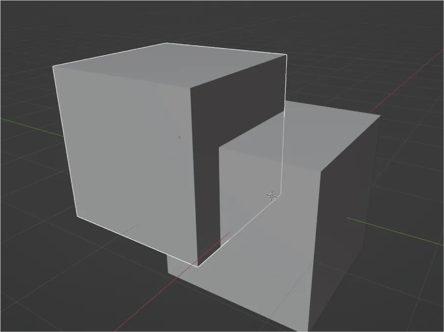
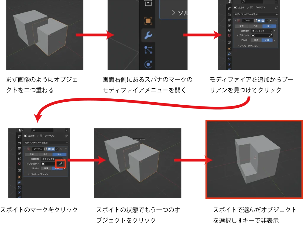
You can duplicate the cube you just selected by selecting it and pressing “Shift+D”. Let’s place it in a place where the two halves overlap.
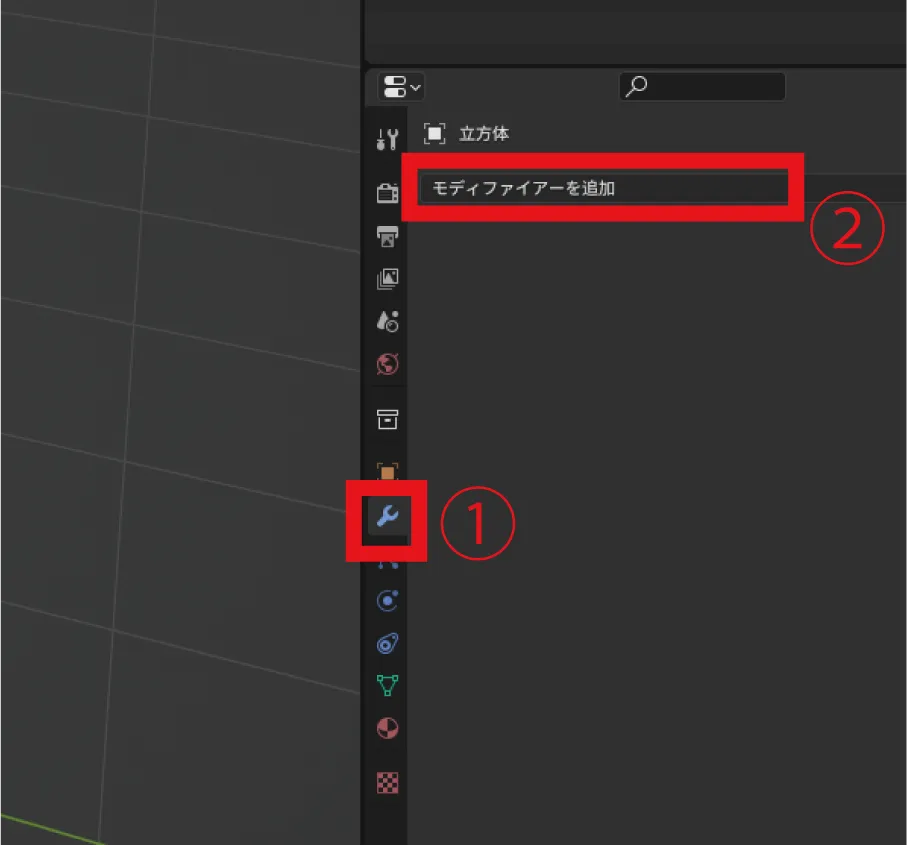
Click the spanner symbol in the menu listed on the right side of the cube of the first one to display the modifier menu.
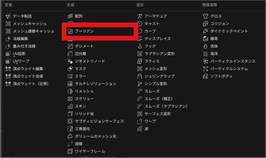
Click on Add Modifier to display the various functions. Select a boolean this time.
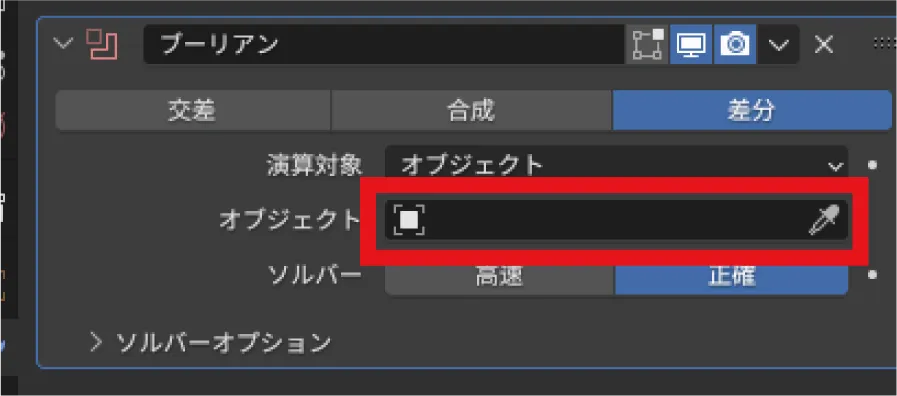
Click on the eyedropper in the box labeled “Object” and the mouse cursor will become an eyedropper. Click on the cube you just duplicated.
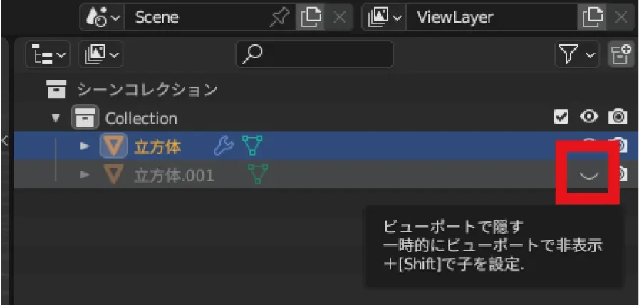
Click on the eye mark of cube.001 in the list in the upper right corner to hide it.
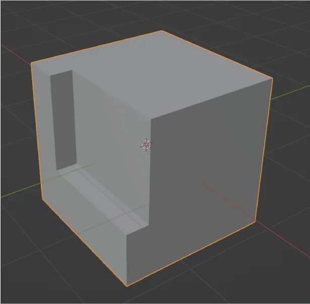
Then it will be shaved in the form of a duplicated cube as shown above.
The convenience of the modifier is that another modifier can be added on top of it from here.
を追加.webp)
From “Add Modifier” as before, now select “Bevel”. You can now add a bevel on top of the previous shaved surface.
You can also change the width and roundness by tweaking the values.
There are various other modifiers that you can try.
Export
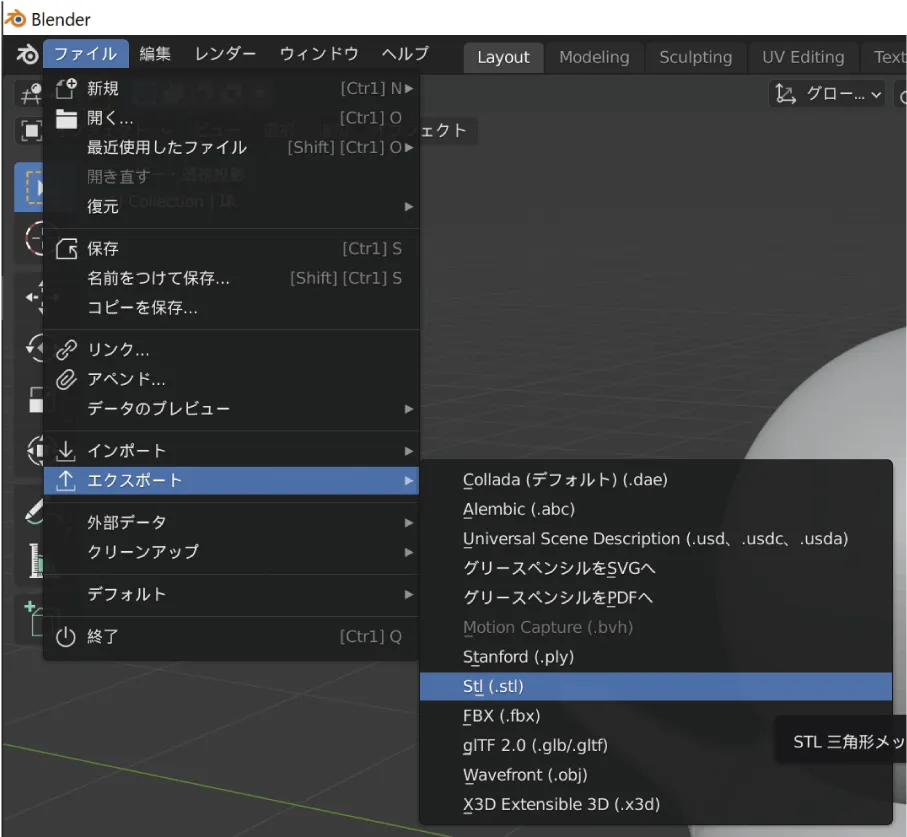
Click File→Export to select the export format.
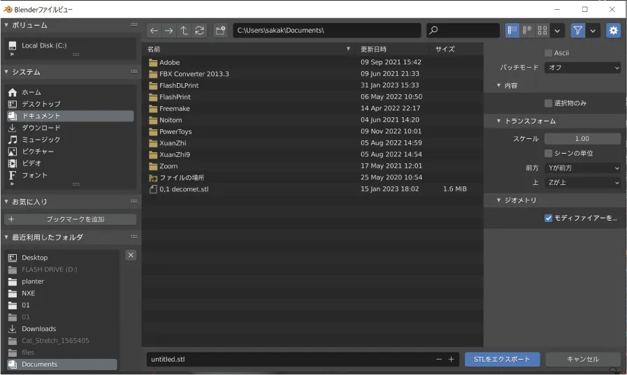
Select the location where you want to save the file and click Export to export.
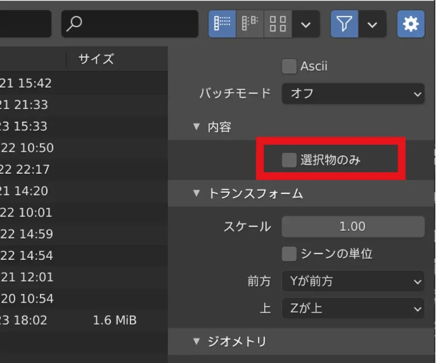
If there are multiple objects in the data and you want to export only one of them, check the “Selected objects only” item before exporting.
[Application] Operations to remember when using Blender
The basic operations have been described above, but from here we will introduce operations that you should keep in mind when using Blender.
Although there are some applications, they are not difficult operations, and if you think of them as extensions of the basic operations, you will be able to understand them smoothly.
Efficient selection in edit mode
First, let us introduce you to the efficient selection methods that are often used in the edit mode.
loop selection
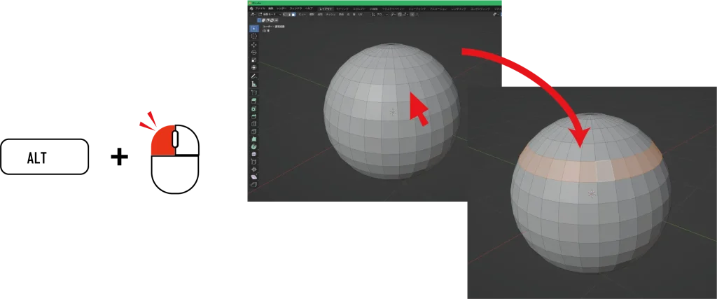
Loop selection differs from normal selection in that it is a convenient way to select edges or faces that are connected in a certain direction all at once.
For example, you can select a loop of edges or faces, or a series of edges or faces that appear to flow, all at once instead of selecting them one at a time.
Select by shortest distance
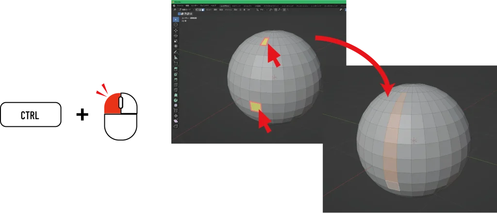
Unlike Loop Selection, Selection at Shortest Distance is a method that allows you to select everything between the two locations you choose. The feature is that the selection is made at the shortest distance between the two selected locations.
Select by object
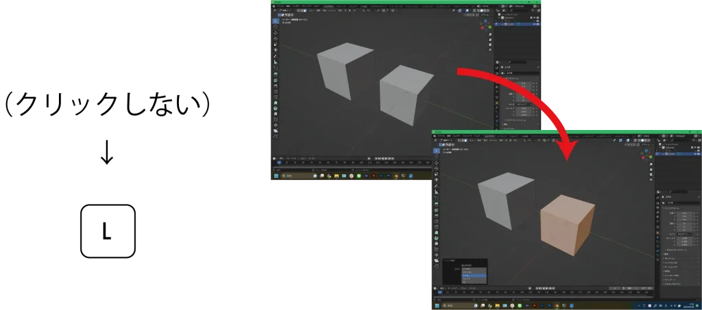
When there are multiple objects in edit mode, it is possible to select one unconnected separate object at a time. This can be done by moving the mouse cursor over the object you want to select without clicking.
Pressing the “L” key selects only the object you want.
hidden
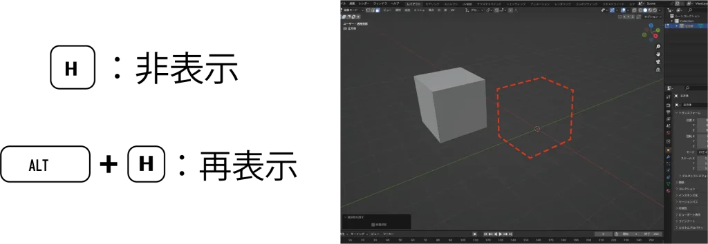
Press “H” to temporarily hide the selected point, edge, plane, or object.
You can restore what you have hidden by pressing “ALT+H”.
The same shortcut can be used in object mode.
Focus display
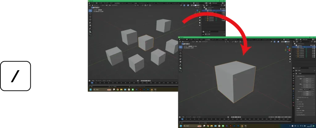
This shortcut makes it easier to see the selected object. It hides all objects except the selected object and brings the viewpoint closer.
proportional editing
When this function is turned on, basic editing of move, rotate, and scale around a selected location can be operated range-wise.

First, click on the “◎” symbol at the top of the screen to turn on proportional editing.
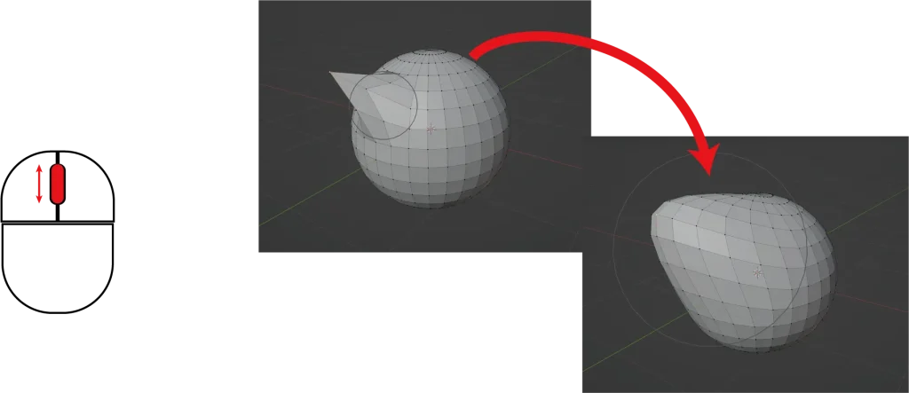
Then select a point, edge, or plane to move, rotate, or scale it. The range of the effect can be specified by turning the mouse wheel.
bridge
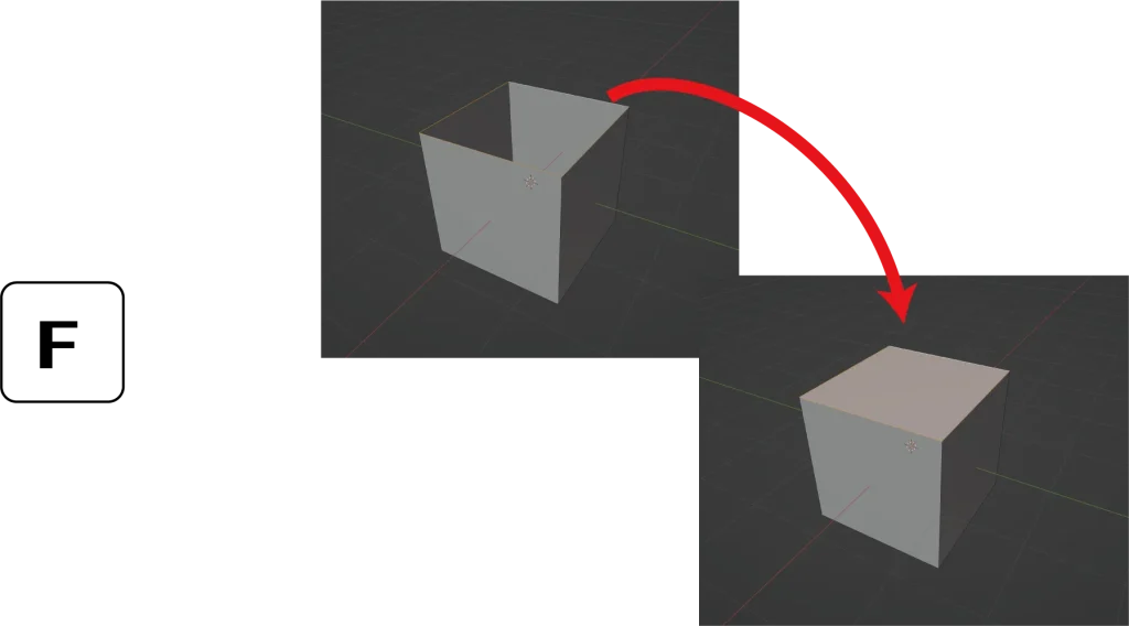
Deleting a part of an object, such as by deleting a face, will result in a model with a hole in it, as shown above.
Select (Alt+click) all the edges around the hole you want to plug. The “F” key on the keyboard can be used to block the hole.
ブリッジの応用
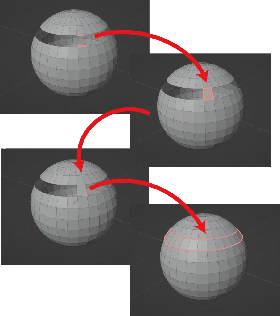
Bridges can also be filled with a series of empty polygons.
First, fill only one side as before. Then, select the empty side of the filled face. Finally, press and hold the “F” key on the keyboard to fill the sides consecutively.
Joints
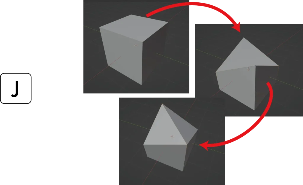
If you edit a point with no edges as shown in the image, you will end up with an object whose shape you cannot tell, so you need to add edges.
To add an edge, select two points to be connected and press the “J” key to connect them with an edge.
Knife Tool
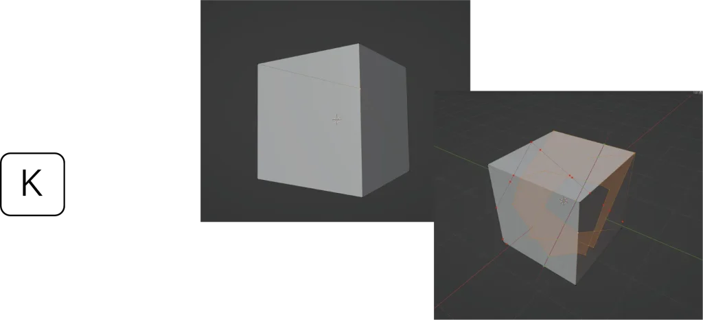
Press the “K” key to change the mouse cursor to the knife tool.
In this state, click on the point or surface where you want to add an edge, and you can add it as shown in the image.
Loop Cut
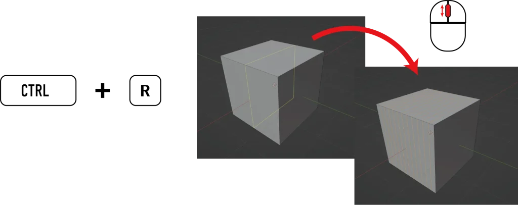
In Loop Cut, you can add an edge to a looping face.
Press “CTRL+R” and move the mouse close to the surface you want to add. Then you can add an edge all the way around, as shown in the image.
You can fine-tune the position by moving the mouse. You can also increase or decrease the number of edges to be added by turning the mouse wheel.
Basically, this function can be used for surfaces that are connected all the way around or for surfaces that have a visible flow, just like a loop selection.
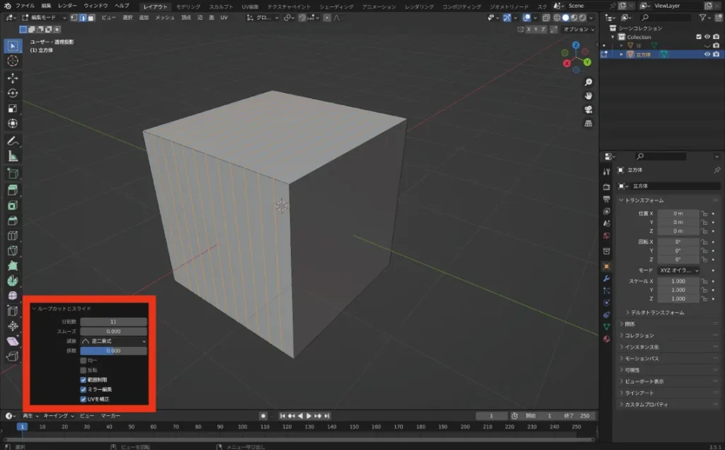
It is also possible to decide the details about the area in the red frame from the menu.
Hebel
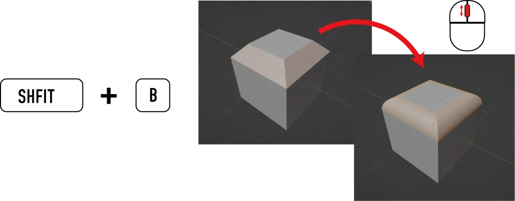
This shortcut allows you to add bevels. First, select the edge to which you want to add a bevel.
Type “SHIFT+B” and move the mouse to add bevels to the corners as shown in the image. You can also round the corners by turning the mouse wheel.
Beveling is always recommended to be done at the end of the modeling process, since it often distorts the object and causes errors.
You can also decide the details of the red frame area from the menu.
Inset
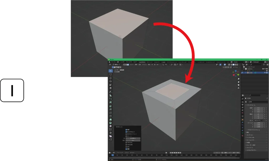
An inset allows you to add a smaller face within a face.
First select the face to which you want to add a face. Press the “I” key and move the mouse to add a face.
Merge
Merging allows you to combine selected points into one.
First, select all the points you wish to merge.
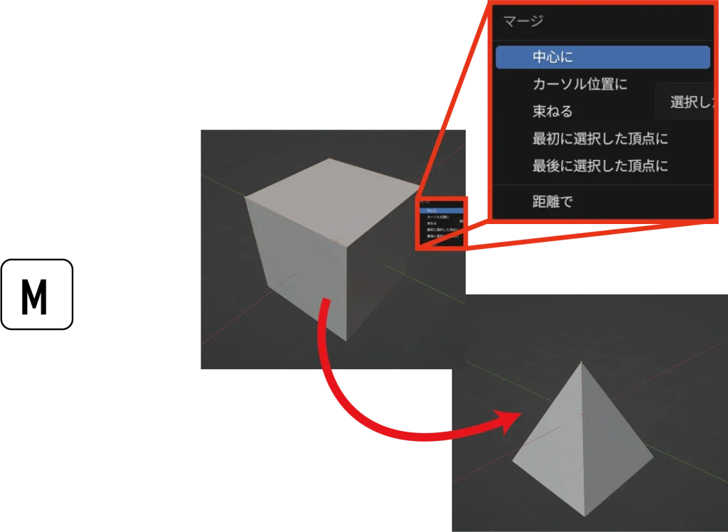
Press the “M” key to bring up the menu shown in the image. Here we choose “In the center” for clarity. Then all selected points will be combined into one point at the center position.
- Centered: Merges all selected points into one point at the location of the center of the selected points
- Cursor position: Merges at the position of the red and white circle (3D cursor) at the origin
- Bundle: Same as Center, but only points connected by a plane are merged.
- First selected vertex: Literally merges at the position of the first point of multiple selections
- Last selected vertex: literally merges at the last point of multiple selections
Merge by distance
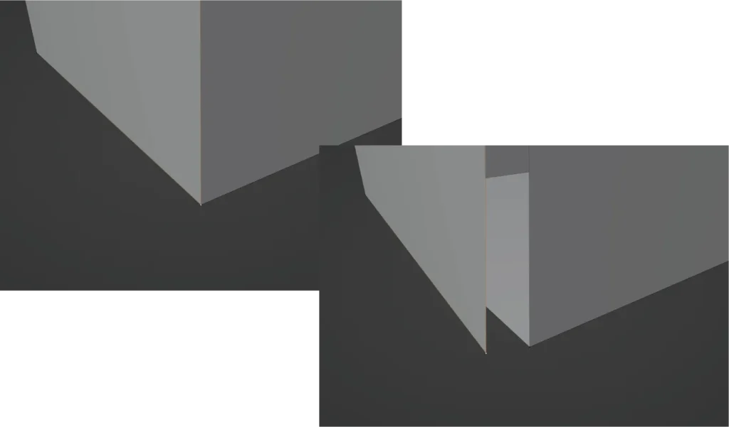
By applying it after selecting all points, it is possible to attach points that do not actually overlap without missing any points, as shown above.
Also, by increasing the merge value by distance, you can gradually group points together to reduce unnecessary points.
How to read dimensions and values
Blender can also display distinct dimensions and sizes in your creation. First, we will explain how to display edge lengths, surface areas, and edge angles.
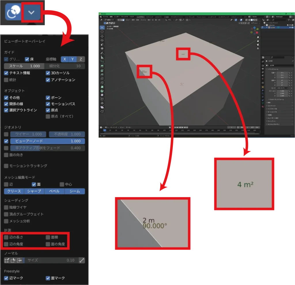
Switch to edit mode and click on the V for View Overlay button in the upper right corner of the 3D View screen.
Then, at the bottom of the Viewport Overlays menu, you will see an item called Measurement.
Click on the checkbox of the item you want to see, and the length, area, and angle of the currently selected part of the object will be displayed respectively.
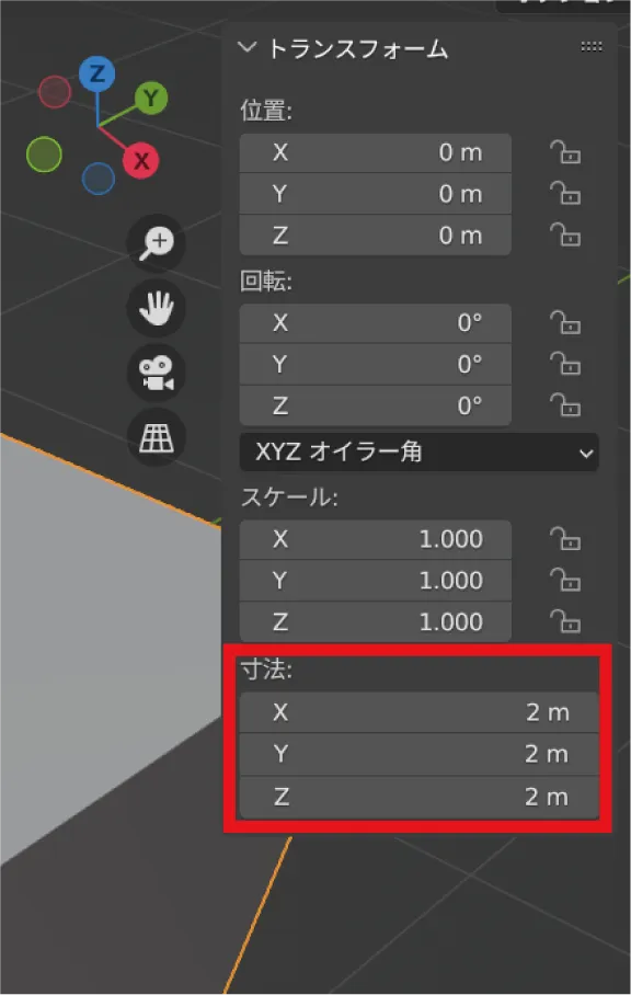
Next, we will show you how to view the dimensions of an entire object.
Switch to object mode, select the object whose dimensions you wish to view, and press the “N” key on your keyboard.
Then a menu item called “Transform” will appear on the right side of the 3D View screen. The dimension shown here is the actual dimension.
By directly modifying the values of these dimensions, you can change the size of the object itself. However, this does not apply to the length of the edges in edit mode, since the object is scaled from its original shape.
If you want to change the size precisely, it is recommended to make sure that all scales above one of the dimensions are set to 1.000 before adjusting them in edit mode.
Modifier
Here we will introduce some useful functions called modifiers that can be used in object mode. Since there are many modifiers, only the relatively useful ones are introduced here.
Note that some modifiers require heavy processing depending on the computer, so please save them frequently when using them.
Boolean
Booleans are used to shave an object with another object or to merge objects together.
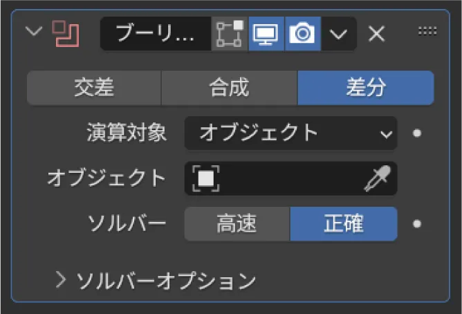
- Difference: Shave with selected object
- Combine: Combine with selected object
- Intersect: Leave only the intersected area with the selected object
Subdivision surface
Subdivision surfaces are modifiers that can smooth rough polygons. It is a quick and easy way to create smooth objects, but should be used with care as it tends to be heavy processing.
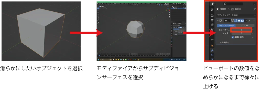
The advantage of the modifier is that it does not change the shape of the original, so the original can be edited as is. Also, if a mistake is made, it can be undone by erasing the modifier.
Decimate
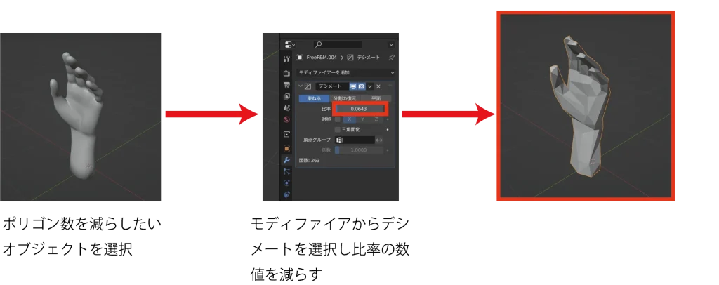
Decimate is a modifier that can reduce the polygon count in high-polygon objects with many points.
It can make objects rougher and can lighten objects with heavy data downloaded from the Internet.
Remesh
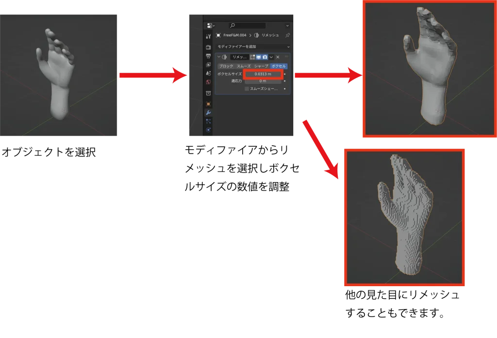
Remesh is a modifier for reconstructing the mesh of an object that has become too complex. It is a modifier version of remesh that is also used in the sculpting tool.
Like Decimate, remesh can also be used to reduce the polygon count.
Mirror
Mirror is a modifier that allows for symmetrical modeling of left and right sides and top and bottom sides. Editing one half will invert the other side and model it the same way.


Overlapping modifier
Since multiple modifiers can be used at the same time, modeling can be done more efficiently by layering them on top of each other.
In the image below, a subdivision surface is applied after mirroring, allowing for symmetrical modeling and smoothing at the same time.
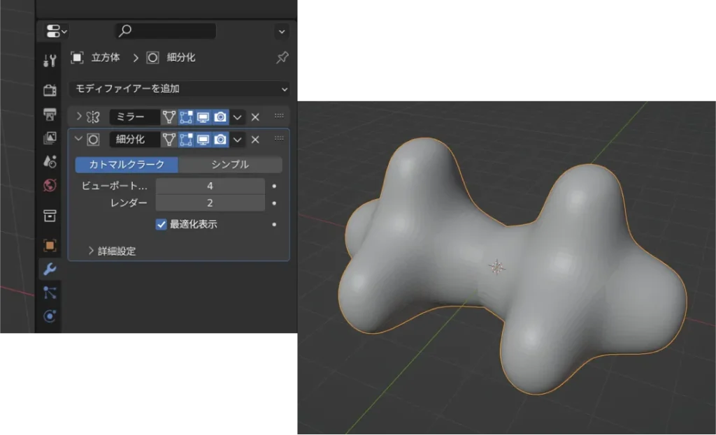
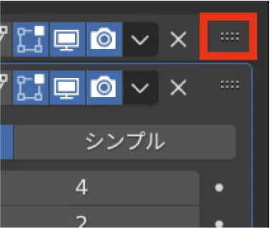
Modifiers are used in order from the top, so if they are used in the wrong order, it may not work. In such cases, the order can be changed by dragging the dots on the right.
Applying Modifiers
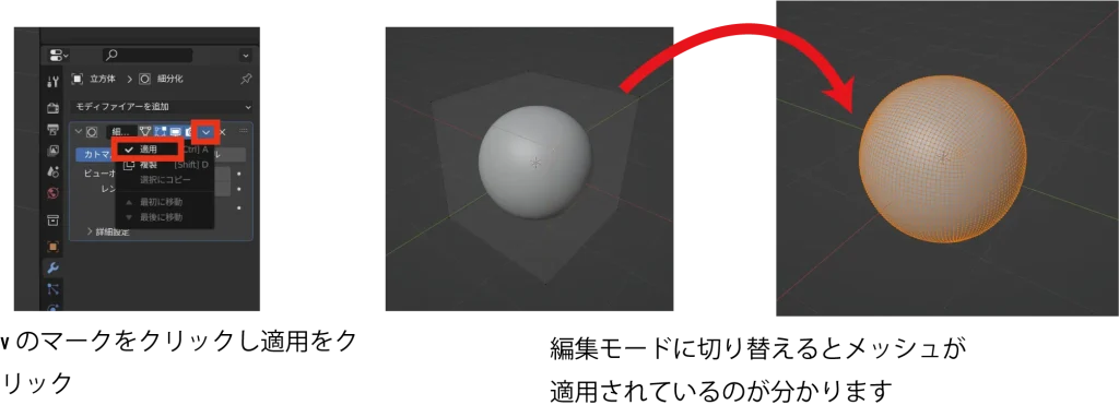
Modifiers are a useful feature, but when used, they can be inconvenient because they do not allow direct editing, such as moving points, edges, or faces.
Therefore, it is necessary to apply it on a case-by-case basis to finalize it in that form.
Once applied, it is difficult to revert the modifier, so it should only be used when absolutely necessary.
Add-on
Add-ons are extensions, and Blender comes standard with a variety of add-ons. There are also various add-ons available on the Internet, some of which require a fee.
Here we introduce what add-ons are.
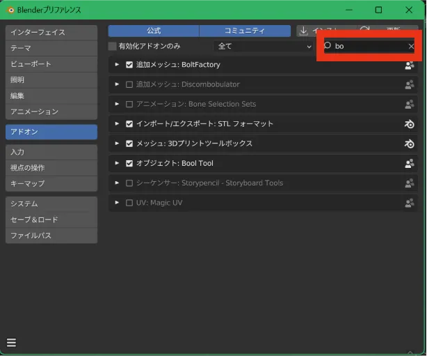
To activate an add-on, open the “Add-ons” section from the “Preferences” window used during the initial setup.
You can search for add-ons by name in the search window in the upper right corner. You can then activate the add-ons you wish to use by checking the checkboxes.
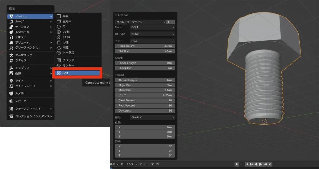
We would like to introduce an add-on called BoltFactory. Once the add-on is activated, a bolt will be added to the Add Object screen. This will allow you to add bolts and nuts without detailed modeling.
You can use the menu in the lower left corner to enter the exact values and create the same shape as the actual bolt.
Let’s learn the basic operation of Blender and touch 3DCG!
We have explained the basic operations of Blender. Blender is a free 3DCG royal-road software, but beginners may find it difficult to operate.
When in doubt, please review this article to master the operations. The shortest way to master it is to learn by touching Blender a lot. Practice and learn as you go.
Team HENSHIN is a video production team with expertise in editing CG and VFX, including 3DCG production using Blender. We provide a variety of information on this website, so please take a look at our other articles.
In addition, we are planning to publish on YouTube and deliver lectures in the future, so we would appreciate it if you could bookmark our site.
Translated with www.DeepL.com/Translator (free version)


